Học Arduino_Dự án 66: Làm một chiếc radar đơn giản bằng arduino và cảm biến siêu âm HC-SR04
- 03/07/2018
- Tự học
Trong dự án này bạn sẽ
Chắc hẳn nếu ai đó nghĩ tới radar là nghĩ tới ngay lĩnh vực quân sự hoặc hàng không,nơi có những dàn antenna,những chảo thu-nhận sóng,nhưng màn hình hiển thị,nói chung là vô vàn những thiết bị to lớn,phức tạp. Thế nhưng trong dự án này,ta sẽ chế tạo 1 chiếc rada vô cùng đơn giản,chỉ với cảm biến siêu âm HC-SR04 đóng vai trò như bộ phận thu-nhận sóng rada được gắn trên 1 servo quay để tạo góc quét. Chương trình viết cho ứng dụng này sẽ gồm 2 phần là chương trình trên Arduino IDE dùng để cho board Arduino có thể xử lý tín hiệu phát-thu từ cảm biến siêu âm,để đưa ra tín hiệu của vật cản và 1 chương trình processing IDE dùng để tạo 1 giao diện trên màn hình máy tính giúp ta hình dung được vị trí vật cản trong phạm vi phát hiện.
Phần cứng
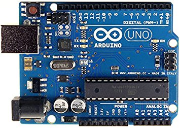
board Arduino Uno
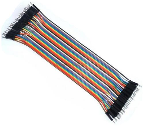
1 test board và nhiều dây cắm test board
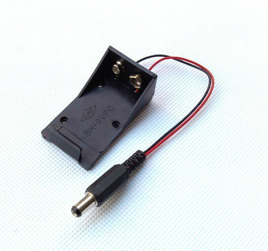
Pin 9v,đế pin và jack kết nối pin với Arduino
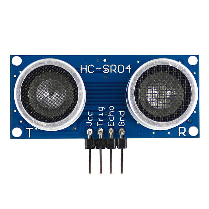
1 cảm biến siêu âm HC-SR04
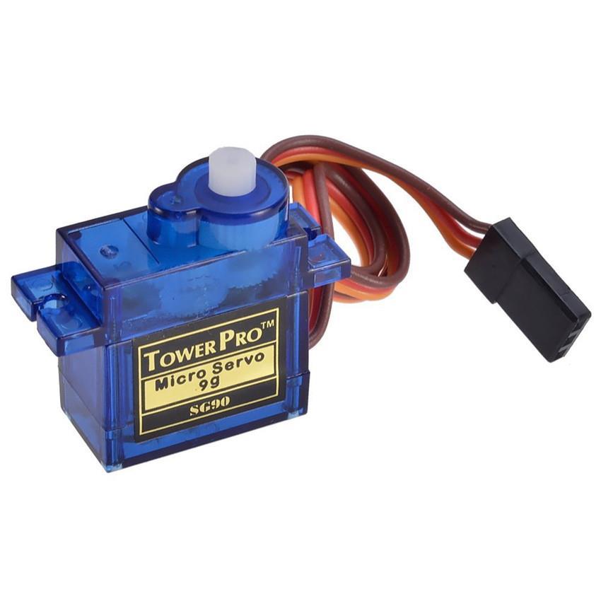
1 servo,ở đây ta dùng loại SG90, góc quay tối đa là 1800
Chắc hẳn nếu ai đó nghĩ tới radar là nghĩ tới ngay lĩnh vực quân sự hoặc hàng không,nơi có những dàn antenna,những chảo thu-nhận sóng,nhưng màn hình hiển thị,nói chung là vô vàn những thiết bị to lớn,phức tạp. Thế nhưng trong dự án này,ta sẽ chế tạo 1 chiếc rada vô cùng đơn giản,chỉ với cảm biến siêu âm HC-SR04 đóng vai trò như bộ phận thu-nhận sóng rada được gắn trên 1 servo quay để tạo góc quét. Chương trình viết cho ứng dụng này sẽ gồm 2 phần là chương trình trên Arduino IDE dùng để cho board Arduino có thể xử lý tín hiệu phát-thu từ cảm biến siêu âm,để đưa ra tín hiệu của vật cản và 1 chương trình processing IDE dùng để tạo 1 giao diện trên màn hình máy tính giúp ta hình dung được vị trí vật cản trong phạm vi phát hiện.
sơ đồ kết nối
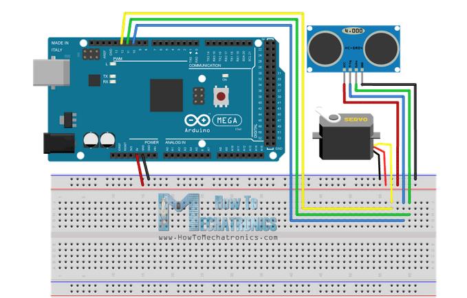
Cảm biến siêu âm đặt trên servo ,cụ thể là cánh tay quay để tạo góc quét cho cảm biến. Sóng siêu âm sẽ được phát ra và thu nhận nhờ hai đầu phát-thu trên cam biến,sau đó tín hiệu,nếu có phản hồi,đầu thu sẽ nhận và truyền tín hiệu về cho board Arduino xử lý.
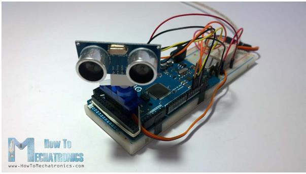
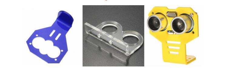
Ta có thể chế tạo giá đỡi ,cụ thể là giá đỡ bằng bìa và cố định bằng ốc lên cánh tay servo
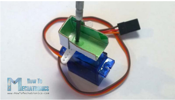
Và sau đó đặt lên như thế này
Ngoài ra,ta cũng có thể gắn cảm biến lên cánh quay của servo bằng nhiều cơ cấu khác có sẵn mà ta có thể thiết kế và chế tạo dễ dàng với công nghệ in 3d
code điều khiển
Để thực hiện project này ta cần tới 2 chương trình riêng biệt để cho phép radar hoạt động và ta có thể theo dõi được. Phần chương trình bao gồm 1 code viết riêng trên Arduino IDE được nạo vào board Arduino để xử lý tín hiệu,ngoài ra,đoạn code này còn cho phép ta có thể xuất dữ liệu trên máy tính, đoạn code thứ 2 được viết trên Processing để có thể tạo ra một dao điện dưới dạng màn hinh quét rada 1800 để ta có thể theo dõi quá trình hoạt động,đoạn code này cũng có chức năng xử lý tín hiệu được Arduino truyền ra máy tính và chuyển nó thành tín hiệu trực quan hơn trên màn hình.
Sau đây là phần giới thiệu về từng chương trình.
Đầu tiên là code cho board Arduino xử lý tín hiệu từ cảm biến
#include <Servo.h>
/*
code for arduino bord ultrasonic radar system.
*/
Servo leftRightServo; // set a variable to map the servo
int leftRightPos = 0; // set a variable to store the servo position
const int numReadings = 10; // set a variable for the number of readings to take
int index = 0; // the index of the current reading
int total = 0; // the total of all readings
int average = 0; // the average
int echoPin = 6; // the SRF05’s echo pin
int initPin = 7; // the SRF05’s init pin
unsigned long pulseTime = 0; // variable for reading the pulse
unsigned long distance = 0; // variable for storing distance
/* setup the pins, servo and serial port */
void setup() {
leftRightServo.attach(9);
// make the init pin an output:
pinMode(initPin, OUTPUT);
// make the echo pin an input:
pinMode(echoPin, INPUT);
// initialize the serial port:
Serial.begin(9600);
}
/* begin rotating the servo and getting sensor values */
void loop() {
for(leftRightPos = 0; leftRightPos < 180; leftRightPos++) { // going left to right.
leftRightServo.write(leftRightPos);
for (index = 0; index<=numReadings;index++) { // take x number of readings from the sensor and average them
digitalWrite(initPin, LOW);
delayMicroseconds(2);
digitalWrite(initPin, HIGH); // send signal
delayMicroseconds(2); // wait 50 microseconds for it to return
digitalWrite(initPin, LOW); // close signal
pulseTime = pulseIn(echoPin, HIGH); // calculate time for signal to return
distance = pulseTime*0.034/2; // convert to centimetres
total = total + distance; // update total
delay(2);
}
average = total/numReadings; // create average reading
if (index >= numReadings) { // reset the counts when at the last item of the array
index = 0;
total = 0;
}
Serial.print(“X”); // print leading X to mark the following value as degrees
Serial.print(leftRightPos); // current servo position
Serial.print(“V”); // preceeding character to separate values
Serial.println(average); // average of sensor readings
}
/*
start going right to left after we got to 180 degrees
same code as above
*/
for(leftRightPos = 180; leftRightPos > 0; leftRightPos–) { // going right to left
leftRightServo.write(leftRightPos);
for (index = 0; index<=numReadings;index++) {
digitalWrite(initPin, LOW);
delayMicroseconds(2);
digitalWrite(initPin, HIGH);
delayMicroseconds(2);
digitalWrite(initPin, LOW);
pulseTime = pulseIn(echoPin, HIGH);
distance = pulseTime*0.034/2;
total = total + distance;
delay(2);
}
average = total/numReadings;
if (index >= numReadings) {
index = 0;
total = 0;
}
Serial.print(“X”);
Serial.print(leftRightPos);
Serial.print(“V”);
Serial.println(average);
}
}
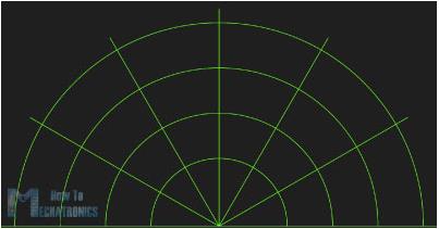
Cuối cùng là phần chương trình tạo nên 1 giao diện mà trên đó ta có thể theo dõi vật cản ở các thông số về khoảng cách cũng như góc,tọa độ mà radar phát hiện ra được,chương trình này được viết trên Processing IDE
/*
Radar Screen Visualisation for HC-SR04
Maps out an area of what the HC-SR04 sees from a top down view.
Takes and displays 2 readings, one left to right and one right to left.
Displays an average of the 2 readings
Displays motion alert if there is a large difference between the 2 values.
*/
import processing.serial.*; // import serial library
Serial arduinoport; // declare a serial port
float x, y; // variable to store x and y co-ordinates for vertices
int radius = 350; // set the radius of objects
int w = 300; // set an arbitary width value
int degree = 0; // servo position in degrees
int value = 0; // value from sensor
int motion = 0; // value to store which way the servo is panning
int[] newValue = new int[181]; // create an array to store each new sensor value for each servo position
int[] oldValue = new int[181]; // create an array to store the previous values.
PFont myFont; // setup fonts in Processing
int radarDist = 0; // set value to configure Radar distance labels
int firstRun = 0; // value to ignore triggering motion on the first 2 servo sweeps
/* create background and serial buffer */
void setup(){
// setup the background size, colour and font.
size(750, 450);
background (0); // 0 = black
myFont = createFont(“verdana”, 12);
textFont(myFont);
// setup the serial port and buffer
arduinoport = new Serial(this, Serial.list()[0], 9600);
}
/* draw the screen */
void draw(){
fill(0); // set the following shapes to be black
noStroke(); // set the following shapes to have no outline
ellipse(radius, radius, 750, 750); // draw a circle with a width/ height = 750 with its center position (x and y) set by the radius
rectMode(CENTER); // set the following rectangle to be drawn around its center
rect(350,402,800,100); // draw rectangle (x, y, width, height)
if (degree >= 179) { // if at the far right then set motion = 1/ true we’re about to go right to left
motion = 1; // this changes the animation to run right to left
}
if (degree <= 1) { // if servo at 0 degrees then we’re about to go left to right
motion = 0; // this sets the animation to run left to right
}
/* setup the radar sweep */
/*
We use trigonmetry to create points around a circle.
So the radius plus the cosine of the servo position converted to radians
Since radians 0 start at 90 degrees we add 180 to make it start from the left
Adding +1 (i) each time through the loops to move 1 degree matching the one degree of servo movement
cos is for the x left to right value and sin calculates the y value
since its a circle we plot our lines and vertices around the start point for everything will always be the center.
*/
strokeWeight(7); // set the thickness of the lines
if (motion == 0) { // if going left to right
for (int i = 0; i <= 20; i++) { // draw 20 lines with fading colour each 1 degree further round than the last
stroke(0, (10*i), 0); // set the stroke colour (Red, Green, Blue) base it on the the value of i
line(radius, radius, radius + cos(radians(degree+(180+i)))*w, radius + sin(radians(degree+(180+i)))*w); // line(start x, start y, end x, end y)
}
} else { // if going right to left
for (int i = 20; i >= 0; i–) { // draw 20 lines with fading colour
stroke(0,200-(10*i), 0); // using standard RGB values, each between 0 and 255
line(radius, radius, radius + cos(radians(degree+(180+i)))*w, radius + sin(radians(degree+(180+i)))*w);
}
}
/* Setup the shapes made from the sensor values */
noStroke(); // no outline
/* first sweep */
fill(0,50,0); // set the fill colour of the shape (Red, Green, Blue)
beginShape(); // start drawing shape
for (int i = 0; i < 180; i++) { // for each degree in the array
x = radius + cos(radians((180+i)))*((oldValue[i])); // create x coordinate
y = radius + sin(radians((180+i)))*((oldValue[i])); // create y coordinate
vertex(x, y); // plot vertices
}
endShape(); // end shape
/* second sweep */
fill(0,110,0);
beginShape();
for (int i = 0; i < 180; i++) {
x = radius + cos(radians((180+i)))*(newValue[i]);
y = radius + sin(radians((180+i)))*(newValue[i]);
vertex(x, y);
}
endShape();
/* average */
fill(0,170,0);
beginShape();
for (int i = 0; i < 180; i++) {
x = radius + cos(radians((180+i)))*((newValue[i]+oldValue[i])/2); // create average
y = radius + sin(radians((180+i)))*((newValue[i]+oldValue[i])/2);
vertex(x, y);
}
endShape();
/* if after first 2 sweeps, highlight motion with red circle*/
if (firstRun >= 360) {
stroke(150,0,0);
strokeWeight(1);
noFill();
for (int i = 0; i < 180; i++) {
if (oldValue[i] – newValue[i] > 35 || newValue[i] – oldValue[i] > 35) {
x = radius + cos(radians((180+i)))*(newValue[i]);
y = radius + sin(radians((180+i)))*(newValue[i]);
ellipse(x, y, 10, 10);
}
}
}
/* set the radar distance rings and out put their values, 50, 100, 150 etc.. */
for (int i = 0; i <=6; i++){
noFill();
strokeWeight(1);
stroke(0, 255-(30*i), 0);
ellipse(radius, radius, (100*i), (100*i));
fill(0, 100, 0);
noStroke();
text(Integer.toString(radarDist+50), 380, (305-radarDist), 50, 50);
radarDist+=50;
}
radarDist = 0;
/* draw the grid lines on the radar every 30 degrees and write their values 180, 210, 240 etc.. */
for (int i = 0; i <= 6; i++) {
strokeWeight(1);
stroke(0, 55, 0);
line(radius, radius, radius + cos(radians(180+(30*i)))*w, radius + sin(radians(180+(30*i)))*w);
fill(0, 55, 0);
noStroke();
if (180+(30*i) >= 300) {
text(Integer.toString(180+(30*i)), (radius+10) + cos(radians(180+(30*i)))*(w+10), (radius+10) + sin(radians(180+(30*i)))*(w+10), 25,50);
} else {
text(Integer.toString(180+(30*i)), radius + cos(radians(180+(30*i)))*w, radius + sin(radians(180+(30*i)))*w, 60,40);
}
}
/* Write information text and values. */
noStroke();
fill(0);
rect(350,402,800,100);
fill(0, 100, 0);
text(“Degrees: “+Integer.toString(degree), 100, 380, 100, 50); // use Integet.toString to convert numeric to string as text() only outputs strings
text(“Distance: “+Integer.toString(value), 100, 400, 100, 50); // text(string, x, y, width, height)
text(“Radar screen code “, 540, 380, 250, 50);
fill(0);
rect(70,60,150,100);
fill(0, 100, 0);
text(“Screen Key:”, 100, 50, 150, 50);
fill(0,50,0);
rect(30,53,10,10);
text(“First sweep”, 115, 70, 150, 50);
fill(0,110,0);
rect(30,73,10,10);
text(“Second sweep”, 115, 90, 150, 50);
fill(0,170,0);
rect(30,93,10,10);
text(“Average”, 115, 110, 150, 50);
noFill();
stroke(150,0,0);
strokeWeight(1);
ellipse(29, 113, 10, 10);
fill(150,0,0);
text(“Motion”, 115, 130, 150, 50);
}
/* get values from serial port */
void serialEvent (Serial arduinoport) {
String xString = arduinoport.readStringUntil(‘\n’); // read the serial port until a new line
if (xString != null) { // if theres data in between the new lines
xString = trim(xString); // get rid of any whitespace just in case
String getX = xString.substring(1, xString.indexOf(“V”)); // get the value of the servo position
String getV = xString.substring(xString.indexOf(“V”)+1, xString.length()); // get the value of the sensor reading
degree = Integer.parseInt(getX); // set the values to variables
value = Integer.parseInt(getV);
oldValue[degree] = newValue[degree]; // store the values in the arrays.
newValue[degree] = value;
/* sets a counter to allow for the first 2 sweeps of the servo */
firstRun++;
if (firstRun > 360) {
firstRun = 360; // keep the value at 360
}
}
}
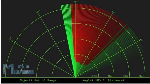
Kết quả,radar sẽ quét qua lại trong 1800 và khi phát hiện vật cản nó sẽ hiển thị màu đỏ ở vị trí tương đối mà radar phát hiện được
Sản phẩm được quan tâm
Nhận bài viết mới
Các bài viết chia sẻ đến cộng đồng rất chât lượng, mang lại rất nhiều kiến thức mới. Đừng bỏ lỡ bất kỳ bài viết nào của chung tối, hãy đăng ký để nhận bài viết mới qua Mail của bạn
Đăng ký để không bỏ lỡ bài viết nào!
Bài mới
- Giáo trình Robocon
- Giới thiệu các loại board Esp8266 dành cho IoT và thiết lập cơ bản cho người mới học
- Hướng dẫn sử dụng LoraEasyV1
- Tài liệu tự học Python tiếng Việt cho người mới bắt đầu
- Tương lai của kết nối IoT (Internet of Things) tiềm năng và sự đa dạng
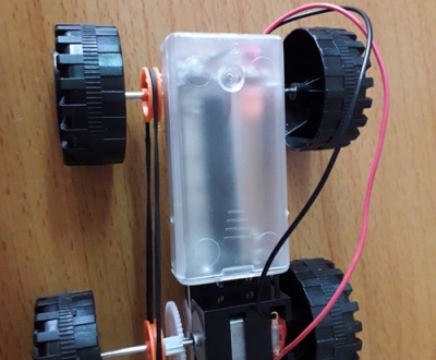
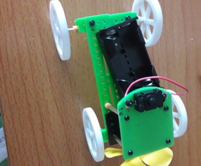
- HƯỚNG DẪN LẤP RÁP XE MÔ HÌNH 4 BÁNH
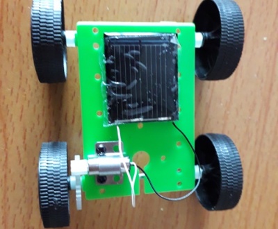
- HƯỚNG DẪN LẮP RÁP XE CHẠY BẰNG NĂNG LƯỢNG MẶT TRỜI
Danh mục